Although the Archimatix Shape Library ships with a variety of parametric shapes, such as Circle, Square, RoundedRectangle, Cross, IBeam, etc., that can be added and subtracted to each other, it may be worthwhile for you to “code” your own Shapes using Turtle scripting and defining your own SceneView Handles.
There are three main areas of focus to consider when authoring parametric shapes:
- Parameters
- Handles
- Logic
This list generally reflects the order of implementation of your custom Shape. When designing a Shape it is useful to create a drawing that helps you (or the users of your Shape) visualize its geometry and the parameters that control it. It is also an interesting exercise to begin with parameters and handles since many geometries can use the same controls.
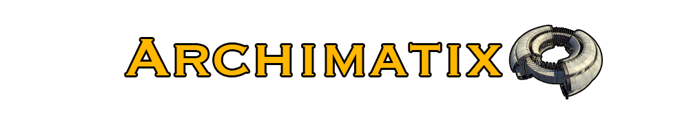
 In the figure to the right, we see an example of a diagram that just shows parameters and handles for a Shape that might be a thought of as a molding profile.
Each handle in the diagram, represented by a red dot, can be defined in the handle editor to adjust certain parameters when dragged. For example, handle B could control both the edge and width parameters while handle A controls only width and handle C controls only the overall height.
These parameters and handles can be added to the node before any scripting is added to actually draw the geometry. In fact, this same setup could be used to control a variety of geometries. Below are some examples.
Particular Shape geometries are based on logic that uses the parameters as variables. The logic is coded using simple turtle graphics scripting implemented right in the node palette.
Using the above molding example, let’s take a look at how to create parameters and handles and then use them with logic.
Adding Parameters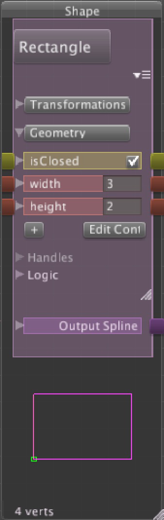
Parameters serve as variables in the logic of the Shape. For example, in a rectangle Shape, the main parameters are width and height. These parameters are then used to position the SceneView handles and as variables in the description of the rectangle in the logic section of the node palette.
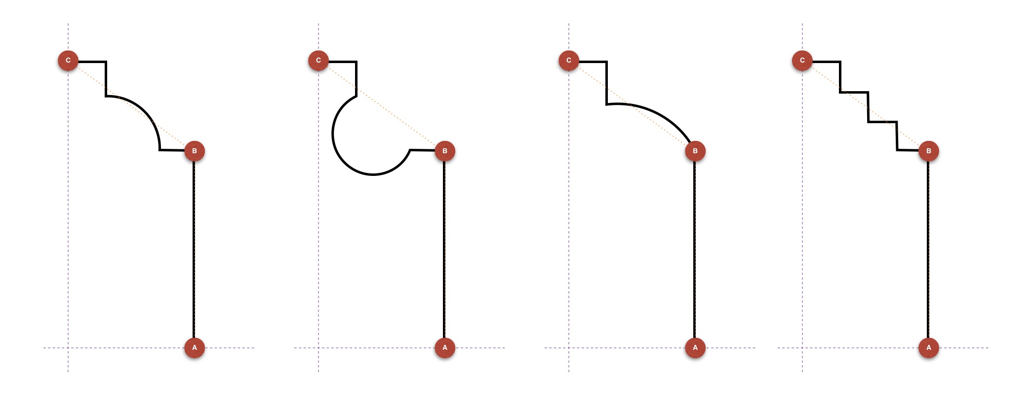
Since we have these same parameters specified in our molding diagram above, it may be best to start our custom Shape with an instance of the Rectangle from the AX Library (choose the Rectangle Shape from the left-hand sidebar of the NodeGraph EditorWindow).
To modify the Rectangle Shape, we will need to add an new parameter called edge. In the Archimatix NodeGraph Editor Window, the parameters are found under the Geometry foldout in the node palette for the parametric shape. You can add as many parameters as you like to the node by clicking on the “+” button at the bottom of the parameter list. Once the add button is clicked, a new parameter will be added to the node and opened for editing.
Naming a Parameter
When the parameter is opened for editing, the name field will be an editable TextField. When choosing a name, be sure not to leave any spaces. This is important since you will need to reference this name as a variable in the script for the Shape’s logic.
For now, we will only edit the parameter’s name, however, you may notice that, in addition to editing the name, you can choose the data type for the parameter (float, int or bool) and start to define expressions for how other parameters in the node should be adjusted if this parameter is modified.
For our molding example, edit the name of the new parameter to be “edge.”
Creating a New Handle
In the Handles foldout of the node palette, you will find a list of named handles. Each of these generates a SceneView handle and defines the behavior of that handle with respect to how it modifies the node’s parameters.
Before adding our new handle, we need to adjust the current width and height handles to adapt them so they are not centered on the origin. Go ahead and click on the width handle and edit the position expression for X to width instead of width/2. Also, adjust the expression to width=han_x. Don’t worry that the Shape is not following these handles yet. Then click on the height handle and set the Y-position to height instead of height/2 and edit the expression so that it is height=han_y.
To create a handle for the edge parameter, click the “+” button under the Handles foldout and name the new handle “edge.” The default type of handle, “Point,” is fine for this. In the position fields, we want to describe where the handle should appear. In this case, the x-position of the handle should be width and the y-position should be the expression height-edge.
After entering these expressions into the x and y fields for Position, the handle should immediately appear in the SceneView, though it is not draggable yet. To make the handle interactive, we have to tell it how to set its parameters when dragged. To do this, edit the first expression for the handle to “width=han_x”. This says that what ever the x-value for the handle is, this should be the value for the width of our Shape. In the vertical direction, we will use the y-value of the handle, or the han_y. Click the “+” button to add a new expression and set it to “edge=height-han_y”.
Now you should be able to drag your new handle and reset the parameters for edge and width.
Logic
Now that we have our parameters (and SceneView handles to modify them), we can use these parameters to “draw” the geometry of our shape.
To draw, we use a sequence of commands that tell the virtual pen tip where to go next from the previous line of script. The mov x y dir command tells the pen to move to the position x, y and orientate itself in direction dir. If the next line of script is fwd 10, then the turtle will draw a line from the starting x,y position to a point 10 units out in the current direction. For a full list of the AX turtle commands available, please see the API.
For our example, let’s start out with a simple molding that features a chamfer. Here is what the turtle script should look like:
mov width 0 90
fwd height-edge
arcl 90 edge 5
fwd width-edge
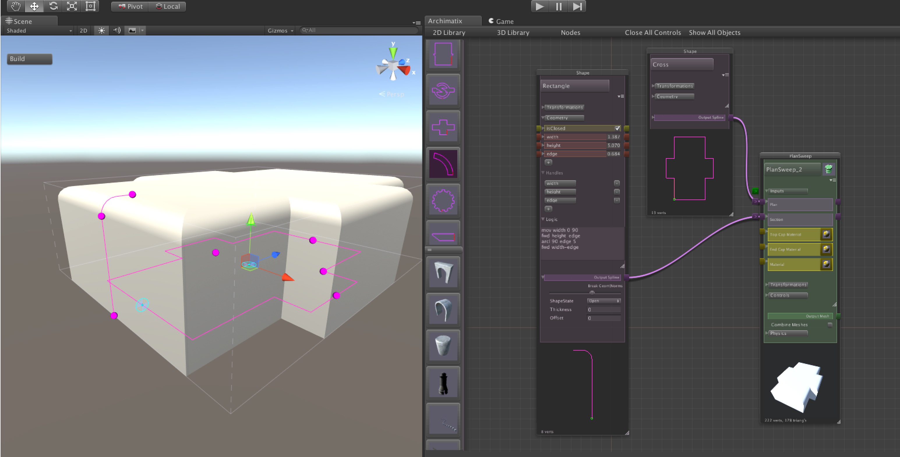
As you can see, after entering this script into the Logic TextArea of the node palette, we are using the parameters, or variables, width, height and edge to draw our Shape. Now, dragging the “edge” handle allows us to generate permutations such as these:
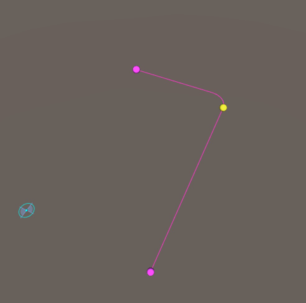
And now the shape is ready to be used for the section of a PlanSweep:
But, what if we wanted the molding to have more detail? Perhaps something to like the first section above with the quarter-round in the bevel. Lets recode the geometry a bit, but with the same parameters and handles.
mov width 0 90
fwd height-edge
left edge/3
arcl 90 edge/3 5
right edge/3
fwd width-edge
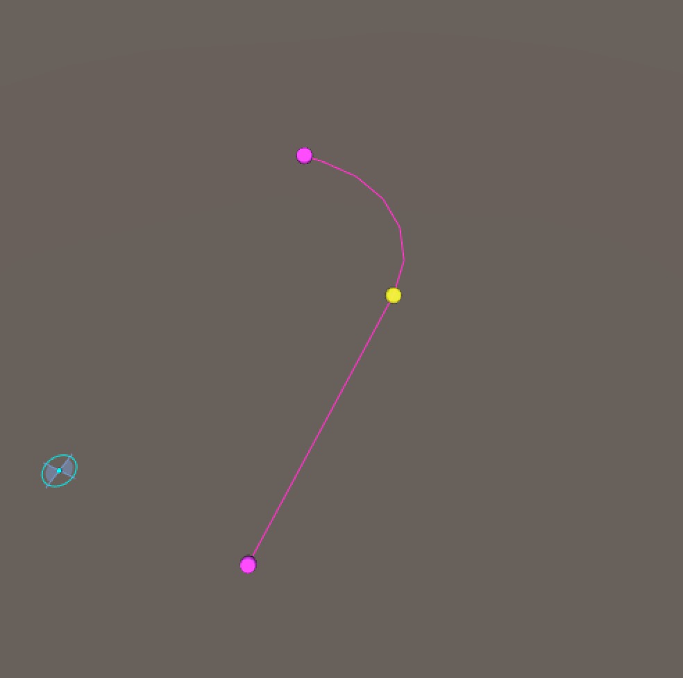
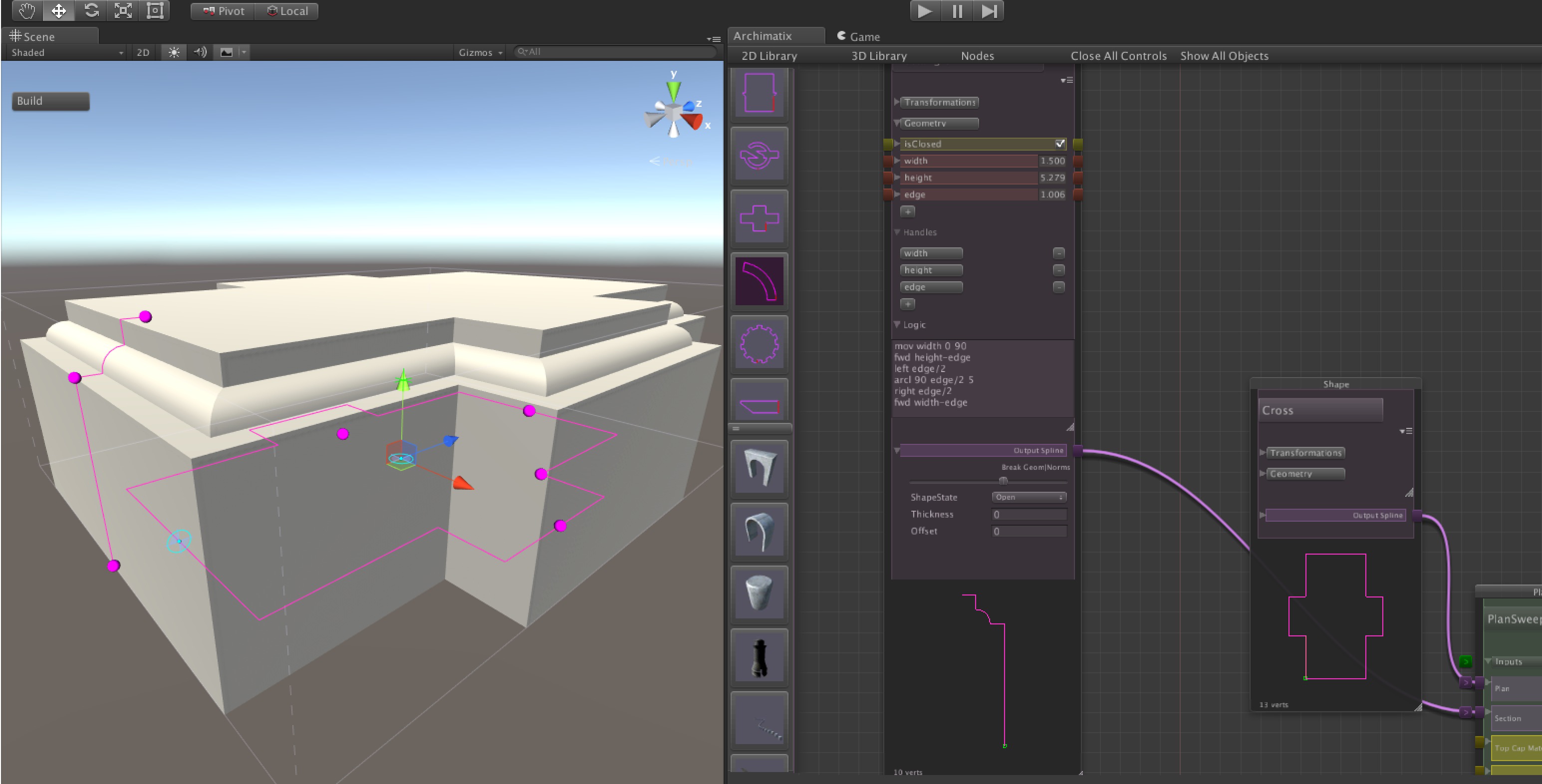
In this version, we have added a bit of mathematical expression such as edge/3. The resulting molding looks like this:
For full documentation on the Archimatix Script API, click here.
Recent Comments