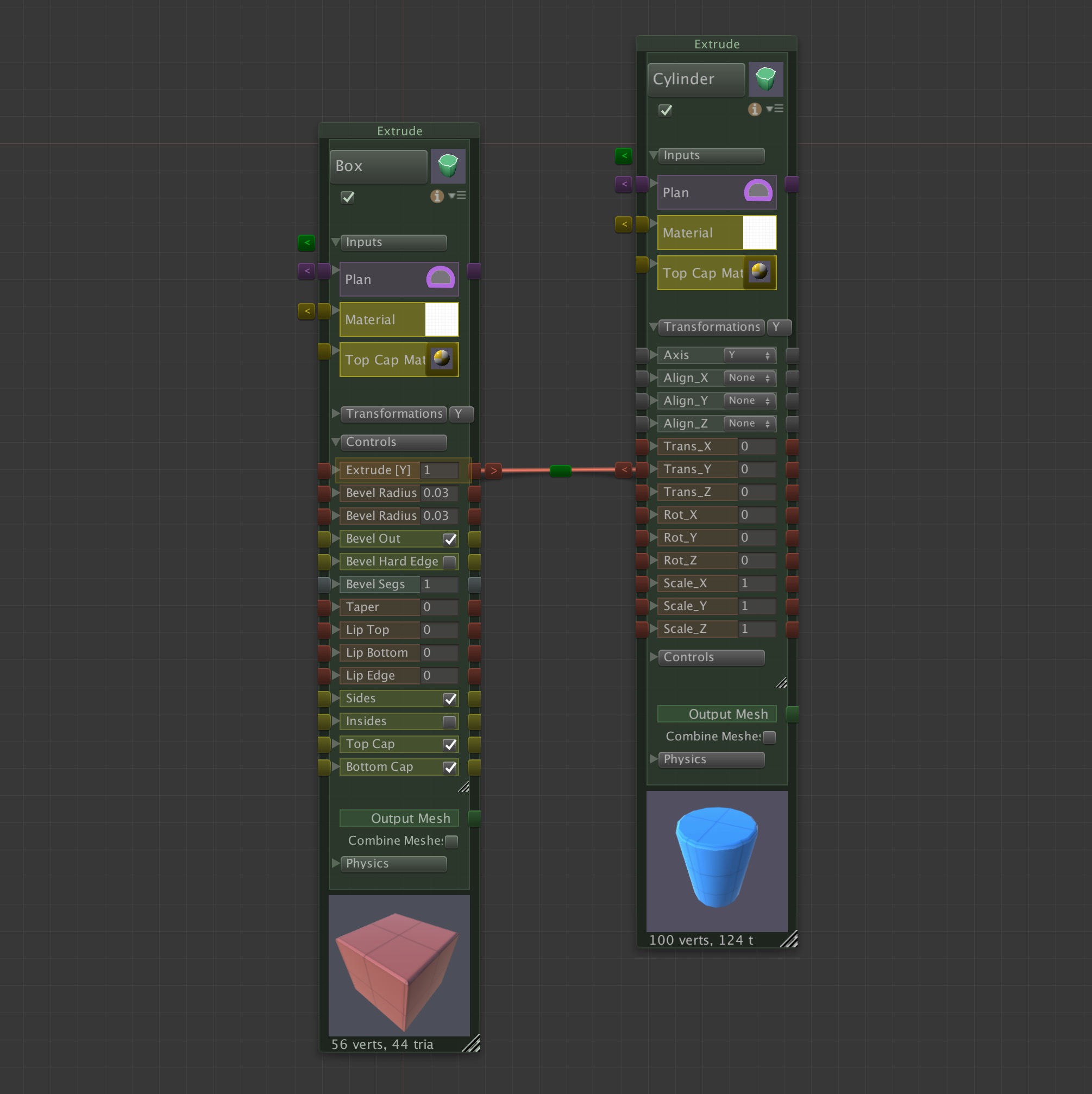
Simple Relation for stacking: the Cylinder is always atop the Box.


Artful parametric modeling is all about managing relationships. Not the personal kind, but the algorithmic kind.
By defining meaningful relationships among your parameters, you can encode a new and powerful morphological genus – creating a new species DNA, as it were, that can be used to generate hundreds of variations of models.
There are two kinds of parametric relations in Archimatix: 1. inter-nodal connections, and 2. parameter expressions. In this tutorial, we will demonstrate inter-nodal connections.
When you connect parameters from different noes to each other, you are authoring behaviors for your parametric model. When you modify one parameter, all sorts of changes may ripple through the model according to the logic you encoded via Relation connections and mathematical expressions within the Relation. Furthermore, these Relations may be bi-directional, meaning that you can change a parameter anywhere in the graph and changes will ripple out from that parameter. The default mathematical expression set when you fist specify a Relation is equivalency, or simply “=”..
Equal Relations
A common case for an equals Relation is when you want one object to always sit atop another, regardless of how tall the bottom object is. In the example to the right, the behavior illustrated is that the blue Cylinder is always atop the red Box.
Try This!
To set up this parametric behavior:
- Choose a Cylinder and a Box from the 3D Library (left sidebar in the NodeGraphWindow.
- Unfold the Controls of the Box and the
A simple “equals” expression.
Transformations of the Cylinder.
- Click on the red connector box on the parameter Extrude in the Box node palette.
- Click on the red connector button next to the Trans_Y parameter on the Cylinder node palette.
- To test: either click on the Box in the SceneView and then drag the green knob to make the Box taller, or click on the Cylinder and then drag the Y-Axis Position Handle.
You will notice that the relation is bi-directional. Modifying either parameter will alter the related parameter. This is a departure from other parametric modelers which feature uni-directional relations. The benefit of bi-directional is that, when playing with a parametric model in the SceneView, you can click just about anywhere you like and start modifying, rather than searching for the “master” parameter.
However, this freedom is not free: the bi-directionality requires inverse expressions to be input. In the case of our simple example, we did not edit the expression found in th relation, relying on the default equals expression. Let’s take a look at how we might make a slightly more complex relation expression.
Expressing Relations
When would like to have more interesting Relations, you can use the ExpressionEditorWindow that pops up when you click on the green button at the center of the Relation connector cable. In the ExpressionEditorWindow are two text fields allowing you to edit the bi-directional relationship between the two parameters.
Try This!
Simple piston with sinusoidal relation to shaft rotation.
Lets say that we would like to simulate the movement of a piston relative to the rotation of a crankshaft in a car engine. The piston rises and falls sinusoidally as the shaft turns. The expression is Piston.Trans_Y=Sin(Crankshaft.Rot_X). Lets go ahead and set this up:
- Choose a Cylinder from the 3D Library.
- Click on the name button at the top of the node palette and rename it “Piston.”
- Use your copy and paste short cuts to create a second Cylinder. Name it “Crankshaft.”
- Next to the Transformations foldout, click the axis button until it show “X.”
- Open the Transformations foldout and choose “Align_X” choose “Center.”
- Click on the Crankshaft in the SceneView and reduce the radius a bit.
- Connect the Piston.Trans_Y to the Crankshaft.RotX.
- Try rotating the Crankshaft – the Piston will continue upward or downward.
- Click on the green button in the middle of the red connector cable.
-
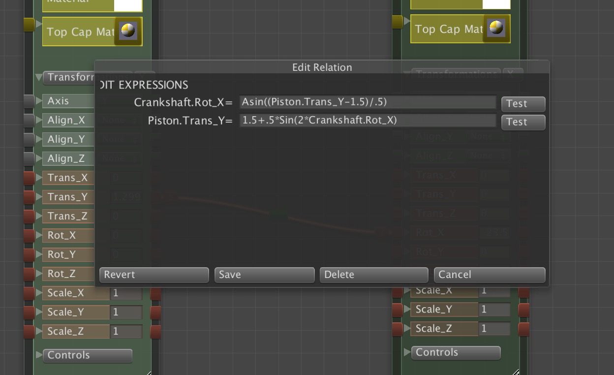
The Edit Relation window lets you define the bi-directional mathematical expression.
In the ExpressionEditor, in the field filled in with Crankshaft.Rot_X, change the expression to: Sin(Crankshaft.Rot_X) and then click on the Save button just below.
- Test by rotating the Crankshaft again. The Piston will oscillate up an down.
- Make the Piston more responsive to the rotation, decrease the stroke and lift it higher above the Crankshaft by editing the expression again to be: 1.5+.5*Sin(2*Crankshaft.Rot_X)
We will save more elaboration on this with the addition of a piston rod, etc. please see the tutorial The Parametric Engine.
Best Practice: Relating Translations
A simple parametric behavior: the red Box and blue Cylinder are always translated to the end of the gold Box.
If you find yourself connecting the Trans_X for one node and the Trans_X of another node to the same source, it is probably better to group the two nodes together with a Grouper and then relate the Grouper’s Trans_X to the source. This is analogous to parenting two GameObjects to an “Empty” GameObject in the Unity hierarchy window. While Archimatix can handle lots of relations, by using relation connections where a grouping would do, you will add more visual complexity to the NodeGraphWindow.
For example, the animation to the right depicts a parametric behavior whereby the red Box and the blue Cylinder are always positioned at the end of the gold Box. There are two ways we could encode this behavior:
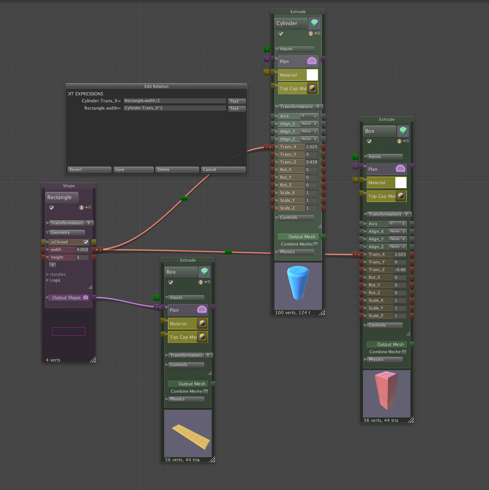
Setting translations for each node will lead to many redundant Relations.
Method 1: This method is not preferable, but happens commonly while building up a graph. The Trans_X of the Cylinder has been related to the width parameter of the rectangular plan of the gold Box with an expression of Cylinder.Trans_X=Rectangle.width/2. When the red Box was added to the graph, a similar relation was added between the gold Box and the red Box, as shown in the figure to the right. Now when we drag the Handle for the Rectangle width, the blue Cylinder and the red Box translate accordingly.
The down side of this is that we have two connections and we have to enter the same mathematical expression twice (for the Cylinder and for the red Box). If we want to change that relationship, we have to change it in two places. Also, the graph will quickly get cluttered if such translations are maintained with Relation connections all the time.
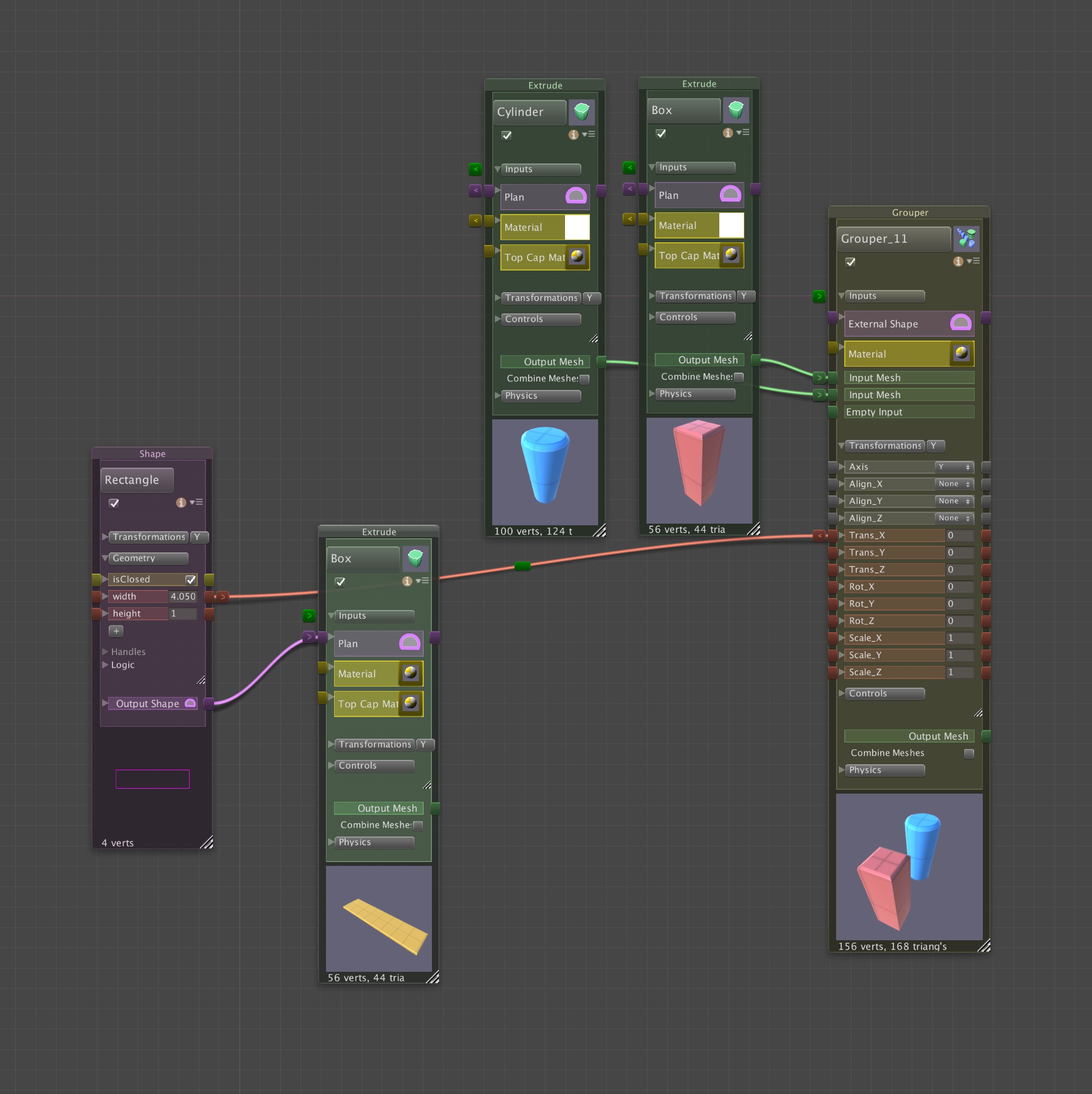
Grouping nodes allows fewer Relations.
Method 2: Alternatively, we can feed the Cylinder and Box into a Grouper and then relate the Trans_X of the Grouper to the width of the Rectangle.
The behavior of our parametric model will be exactly the same, but now, if we wish to edit the expression in the relations, we are editing in only one place. Also, the graph will have fewer parametric relations, which tends to make the graph more legible.
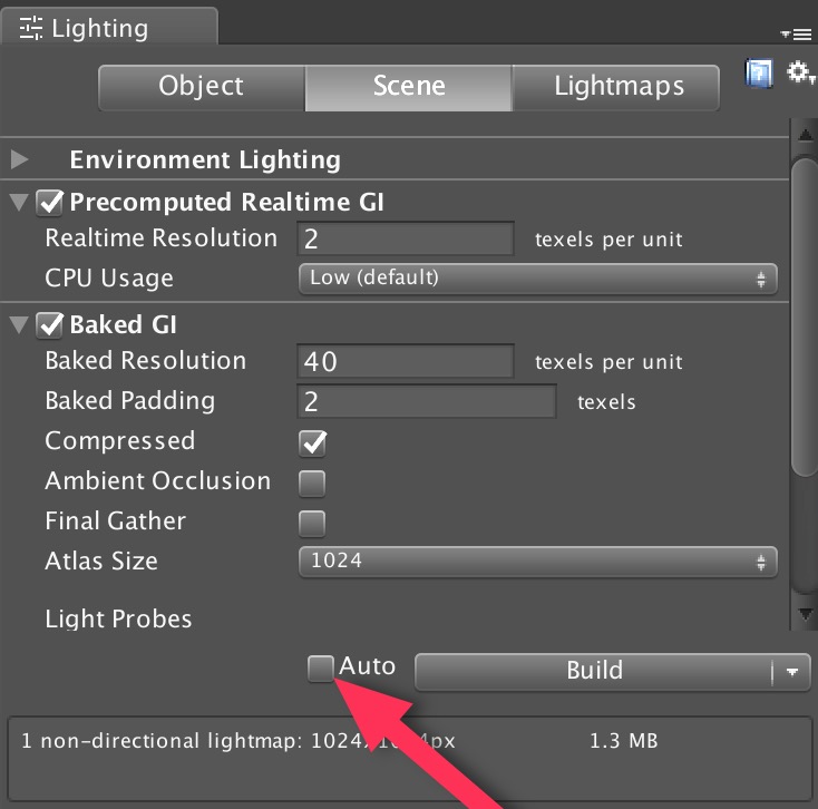 The first way to avoid unnecessary computation while modifying the parameters of a model is to simply turn the Auto build mode off. This is done by opening the
 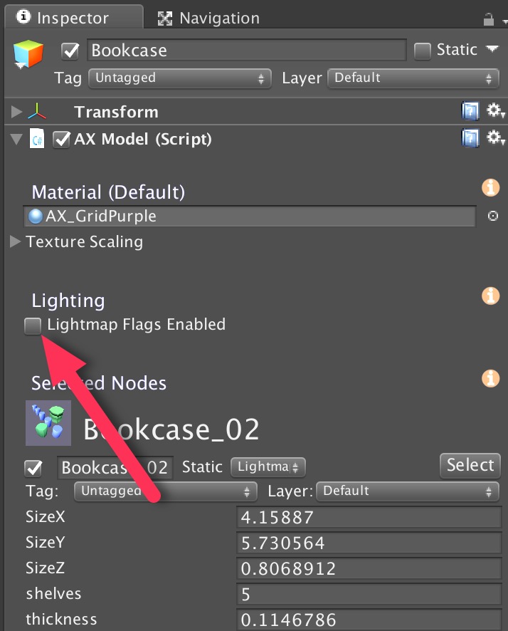 However, if you have a preference to leave “Auto” on, then you can temporarily disable Lightmap Static flags for your entire AX model by making sure the Lightmap Flags Enabled checkbox in the Inspector for the model is off. This means that, as AX generates GameObjects with meshes, it does not add the Lightmap Static flag to the the GameObjects and the light mapper will not be aware of the changes to the mesh. With this approach, you can model as much as you like, and then when ready to see it rendered with GI, you can click the Lightmap Flags Enabled checkbox.
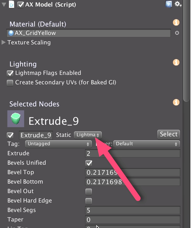 If a AX ParametricObject, such as the Extrude_9 in the figure to the right, is set to LightmapStatic (red arrow), then when a GameObject gets generated AX, its static flag will be set to Lightmap Static (so long as the Lightmap Flags Enabled is checked when the model is built), and the Unity GI system will treat it as such when rebuilding. This static flags setting is analogous to the flag options for any GameObject in Unity, with the difference being that the flag is set internally in the AX node and transferred to GameObjects when they are built by AX.
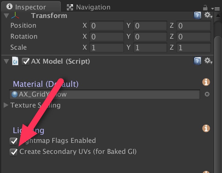
Recent Comments