Turtle graphics, originally developed as a feature in the Logo programing language, is an important tool for the description of line shapes. Each line of a turtle script draws a 2D line relative to the current position of the turtle cursor. While this may seem conceptually simple, it is a powerful concept in parametric graphics. For example, to draw circular arc, with five segments, one need not calculate each of the five vertices, if one can simply tell the turtle to draw an arc to the right through 45 degrees at a radius or 3 units. The command in turtle script may look like this.
arcr 45 3 5
Archimatix has its own implementation of a turtle scripting API, borrowing more closely from GSDL, a 4th generation language developed by GIST, Inc., than from Logo.
Absolute Commands
mov x y <a>
Before drawing a shape, we have to place the turtle somewhere in 2D space and point it in a certain direction. This command moves the turtle to the point x, y with out drawing any lines. The optional argument a tells the turtle in which direction to face. The default direction is 90 degrees.
dir a
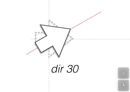
This command, which reorients the turtle to a new direction, can be called anywhere in the script whenever you would like it to abruptly change direction.
drw x y
Draw a straight line from the current point to x, y.
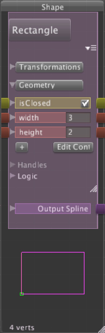
closed true|false
Closes the shape. Shapes are open by default. Note that you cannot yes an “=”, only a space between the function and the value.
//
Comments in follow the standard double-slash. Any text after this will be ignored by the script parser.
Relative Commands
rmov dx dy
Moves the turtle pen tip to a new point and resets the current direction to the line from the pervious to the moved point..
turnl a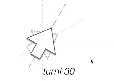
Turns the current direction a degrees to the left.
turnr a
Turns the current direction a degrees to the right.
fwd c <d >
>
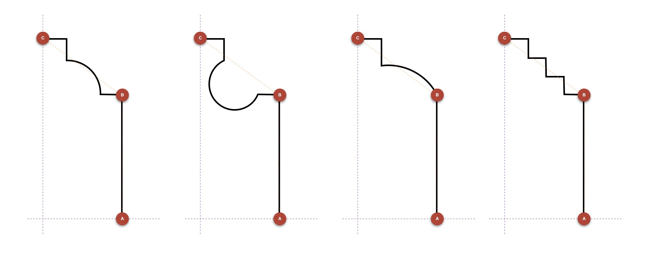
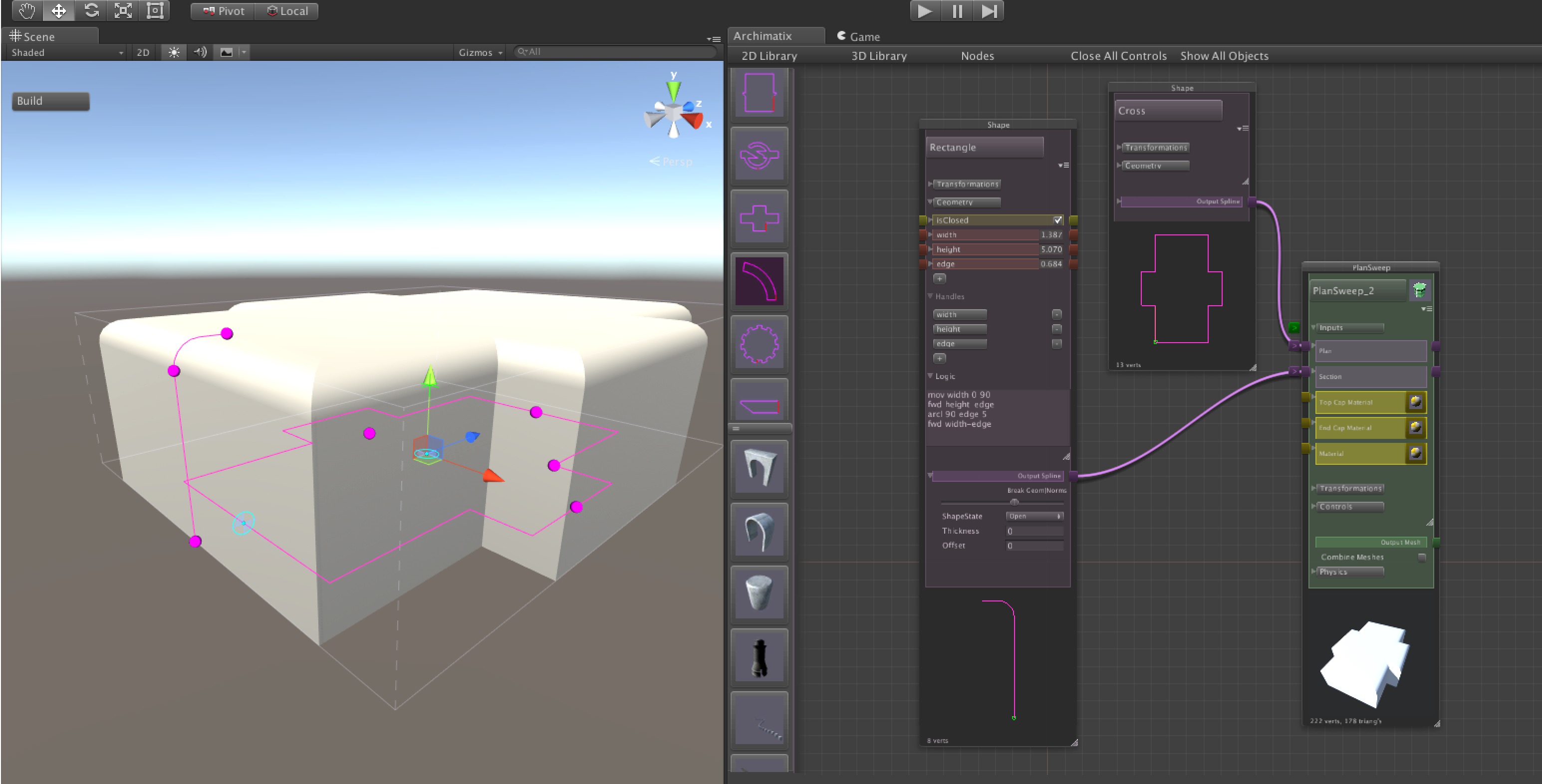
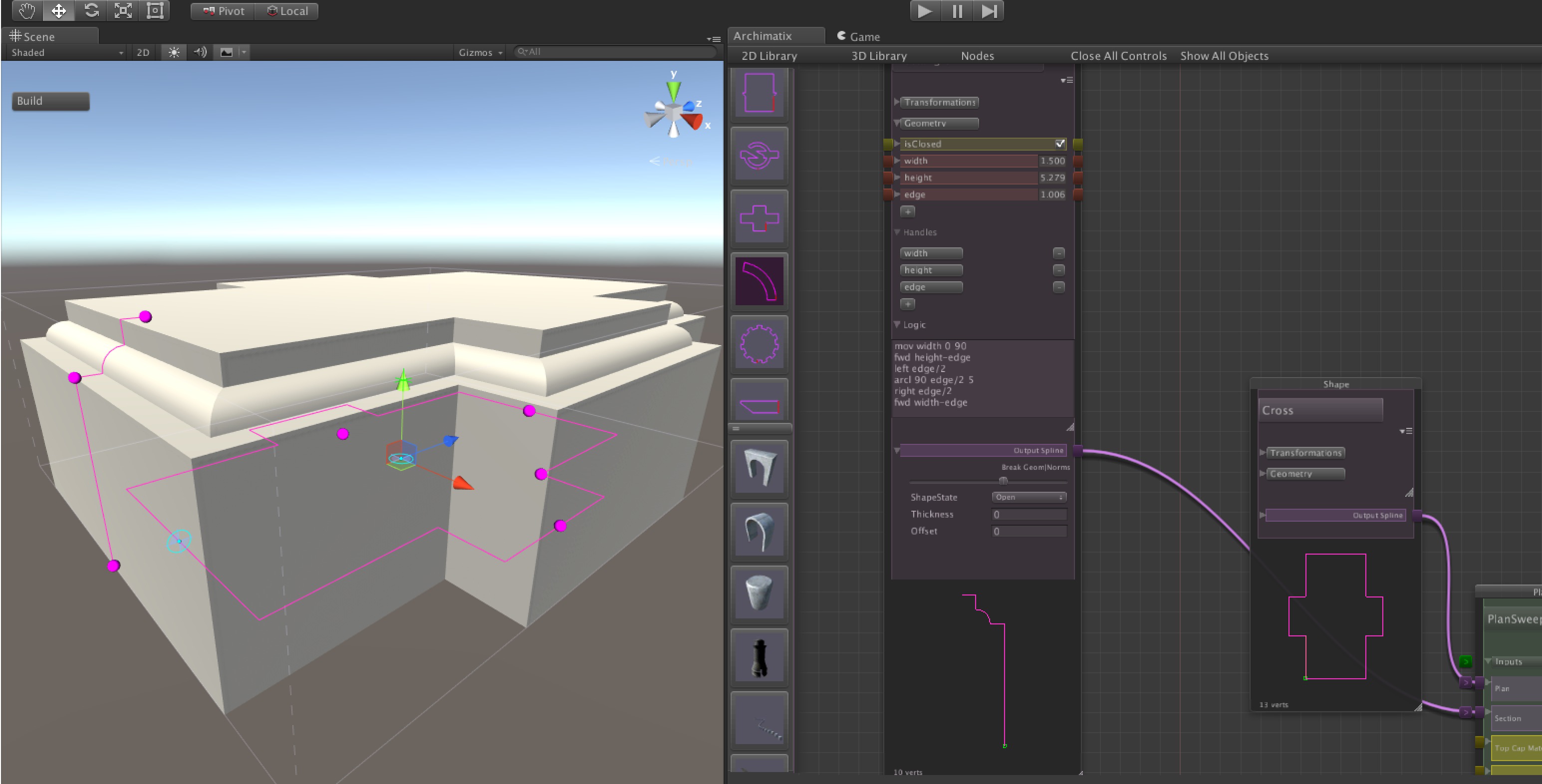
Draws a line c units long in the current direction. For example, fwd 30, or if using a parameter, fwd height. Optionally, d offsets the point from the directional axis so that a diagonal line will be drawn c units forward and d units perpendicular to the current direction. This offset is useful for drawing a shape that fits with in box, but that has corners chipped off, so to speak.
For example, this is a box with the two top corners inset:
mov 0 0 angle
fwd height/2
fwd height/2 -inset
left width-2*inset
back height/2 inset
back height/2
back c <d>
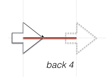 Draws a line c units long, backwards, or in the opposite of the current direction.
right c
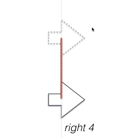 Draws a line c units long to the right, without changing direction.
left c
Draws a line c units long to the right, without changing direction.
arcr a r s
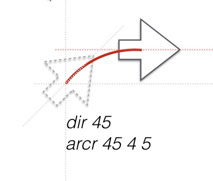 Draws a circular arc of a degrees, with a radius of r, beginning at the current point and tangential to the current direction and arcing to the right. After the command is execute, the turtle’s direction is automatically turned to the tangent of the end of the arc. For example, with a dir 45, arcr 45 3 5 will leave the turtle at a direction of 0 degrees so that if you follow with a fwd 4, the turtle will draw a line 4 units long at an angle of 0 degrees.
arcl a r s
Similar to arcr, but curving to the left.
Mathf Functions
All of the Mathf Functions have been mapped to AX Turtle Script. They follow the general form of:
cos(degs)
or
Cos(degs)
A rad2degs conversion goes on inside the function, so the argument is in degrees.
Another example is
atan(x, y)
Mathf variables can also be used in your equations such as x*PI
PI
degs2rad
Looping
AX Script has a limited looping syntax that basically repeats the code with a counter.
loop repeats <counterName> <step>
The loop command opens the scope of the loop. The repeats argument specifies the number of times to run through the loop. Th optional counterName is a string name for the internal counter variable. The optional step is a number or expression that tells the loop how much to advance the counter by each time.
endloop
Teminates the scope of the loop.
In this example, the loop will draw a dotted line with 10 unconnected segments. The counter variable i multiplied by span will start an unconnected line segment every 5 units with a segment length of 2.5.
let segs 10
let span 5

loop segs i
    mov i*span 0 90
    fwd span/2
endloop
In this example of a parametric gear shape, the loop will draw a gear shape with teeth number of teeth. No counterName is needed here.
let degs 360/(2*teeth)
mov radius 0 90

loop teeth
    arcl degs radius segs
    right tooth
    arcl degs radius+tooth segs
    left tooth
endloop
Note that in the above gear, all variables are Parameters in the node except for degs, which is a temporary variable defined in the script.
This example will produce a stair shape:
loop steps-1
fwd ariser
left tread
endloop
Conditional Block
The conditional command does not use parentheses. There is currently no else or else if, though they are planned.
if var1 GT var2
You can also reference a bool parameter
if bool
endif
Closes the conditional block.
The conditional uses the boolean operators:
LT for "less than"

LE for "less than or equal to"

GT for "greater than"

GE for "greater than or equal to"
EQ for "equals"

NE for "not equals"
There is currently no elseif, else, continue, or break but theses are planned. The workaround for else is to create a second block with the opposite conditional.
end
Terminates the turtle script execution early.
Parameter and Variables
set parameter value
The set command will set a parameter based on the parameter’s name. This is particularly useful for defining a max and min value for a parametr.
set width greater(width, .01)
Or for making sure a parameter never rises above another:
set width lesser(shaftHeight, columnHeight)
Thus, even as the user drags a handle or types a value in a float field, it will not break the rule defined in the set command.
let tempVar value
The let command defines or resets a temporary variable. This is useful in the case that you have a long expression that you need to use in multiple function calls while drawing.
let buildingLength sine(angle)*buildingHeight
To reset a temporary variable, you must use let again.
let buildingLength 5
Special Variables
DetailLevel - This is a read-only variable that reflects the current detail level setting for the model.
Absolute Commands (Cont.)
Special Curves
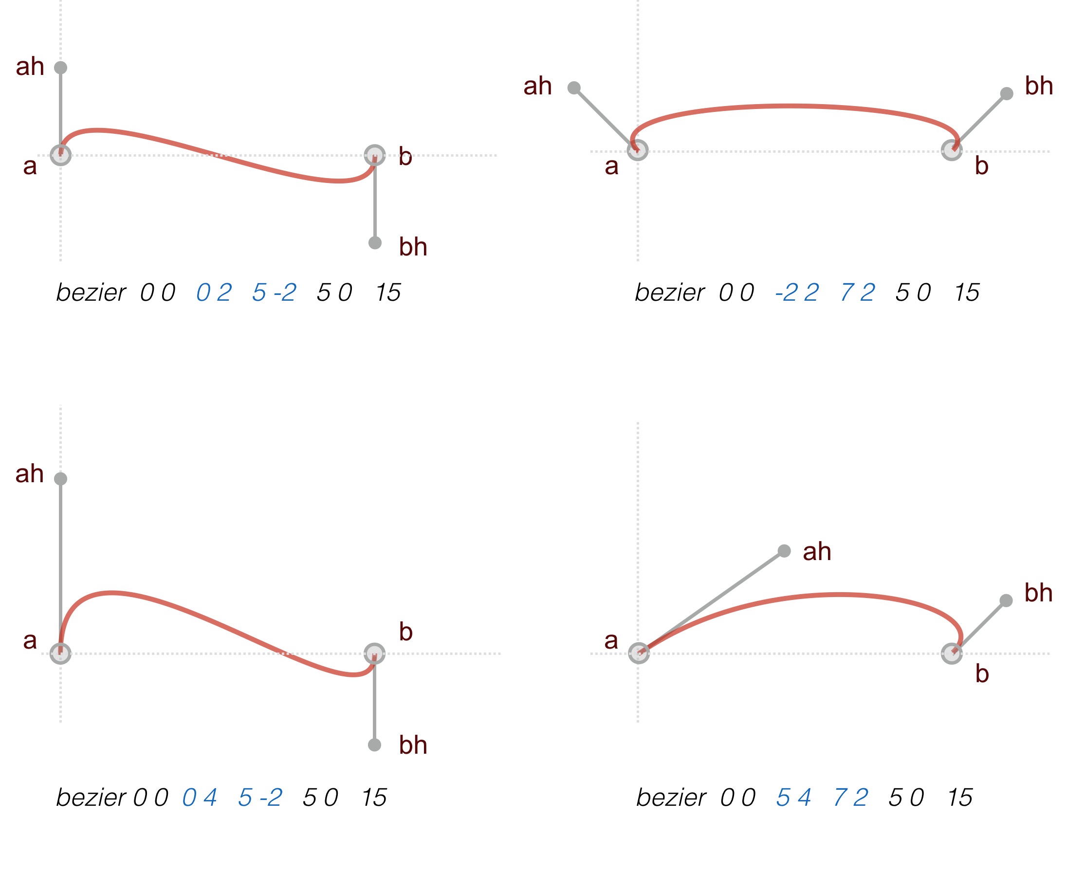
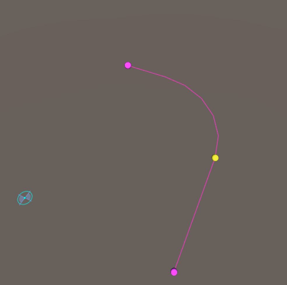
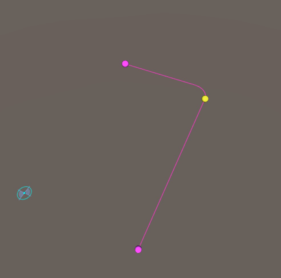
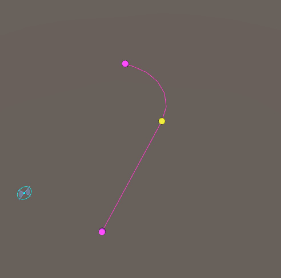
bezier ax ay ahx ahy bhx bhy bx by segs
Draws a cubic Bezier curve between points a and b. The curve is modified by handles defined by absolute endpoints ah and bh.
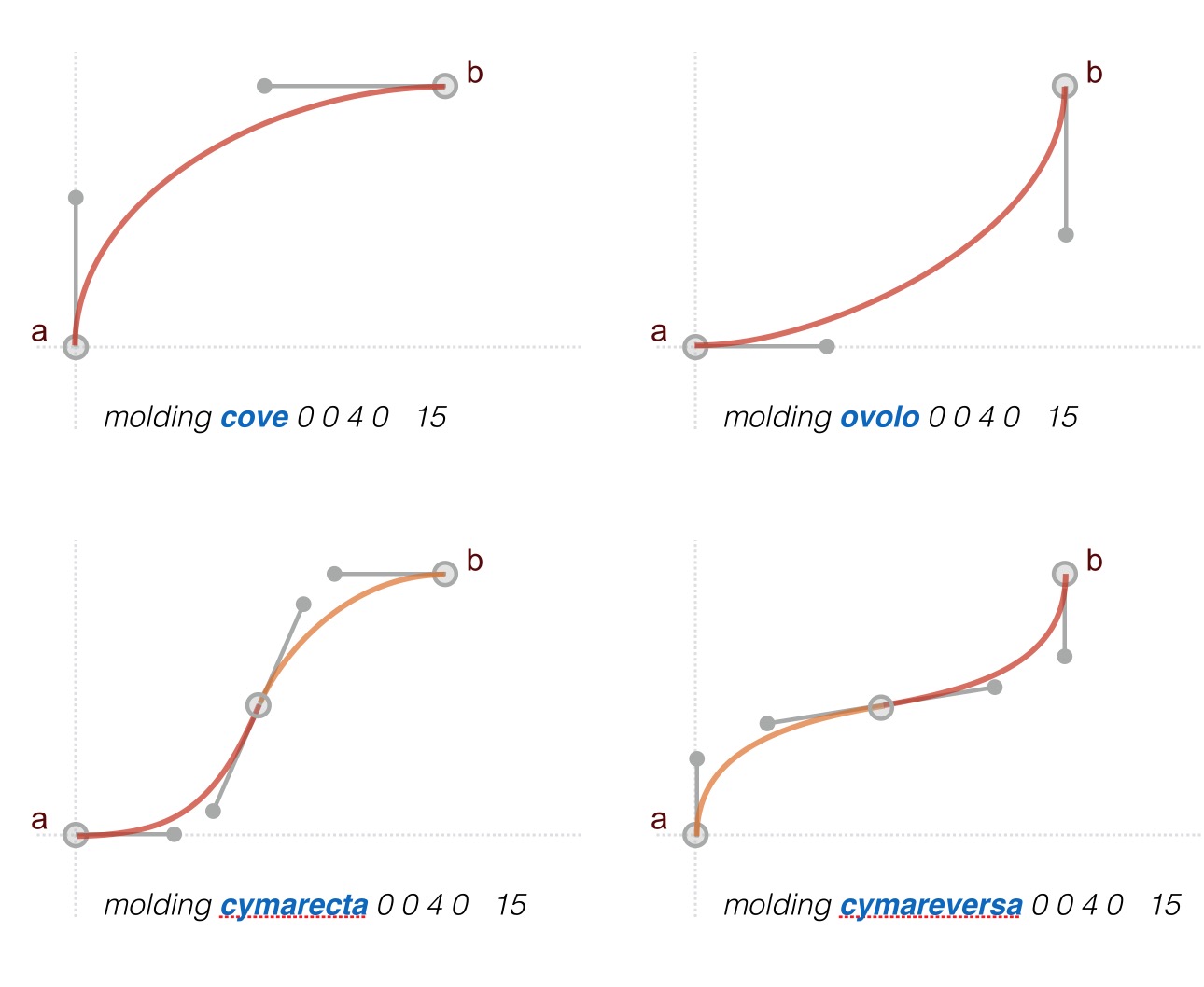
molding type ax, ay bx, by segs, tension
Moldings profiles are Shapes that have a very common use in architecture. This command uses one or more bezier curves to and makes certain assumptions about the handles so that you do not have to construct a sequence of beliers curves yourself. Borrowing from the timeless art of molding design, we have a few types that can be called in the molding command, including cove, ovolo, cyma recta, cyma reversa and onion.
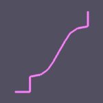
CymaRectaMolding
An example of the molding command can be seen in the Turtle script for the 2D Library item CymaRectaMolding, which adds a square base and an apple lip to the basic molding curve of type “cymarecta”.
Mathf Functions
AX Turtle script also includes many of Unity’s Mathf functions. They are implemented as a straightforward mapping. For example, Mathf.Abs(float f) is written in AX script as:
let val=Abs(float f)
//or, for each function call, you can use lower case as well.
let val=abs(float f)
The Mathf functions currently implemented are:
Mathf Constants:
Mathf Functions
Abs(var)
Acos(var)
Asin(var)
Atan(opposite/adjacent)
Atan2(opposite, adjacent)
Ceil(var, a)
CeilToInt(var)
Clamp01(var)
Cos(var)
Exp(var)
Floor(var)
FloorToInt(var)
Lerp(a,b,time)
Max(var, a)
Min(var, a)
MoveTowards(var, a, b)
MoveTowardsAngle(var, a, b)
Pow(var, a)
Repeat(var, a)
Round(var)
Sign(var)
Sin(var)
Sqrt(var)
Tan(var)Synonyms
Int(var) // Synonym for Mathf.FloorToInt(a)
range(var, a, b) // Synonym for Mathf.Clamp(var, a, b)
greater(a, b) // Synonym for Math.Max(a, b)
lesser(a, b) // Synonym for Mathf.Min(a, b)
Other Functions
modulo( float, int)
// modulo gives the remainder form a division. The c# modulo expression 90%30 would give 0, meaning 30 is a multiple of 90. In AX script, this would be modulo(90, 30)IsEven(a) // shortcut for (a % 2) ? 0 : 1;
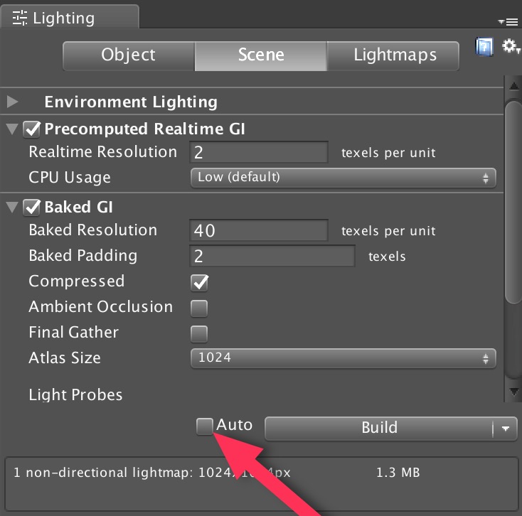 The first way to avoid unnecessary computation while modifying the parameters of a model is to simply turn the Auto build mode off. This is done by opening the
 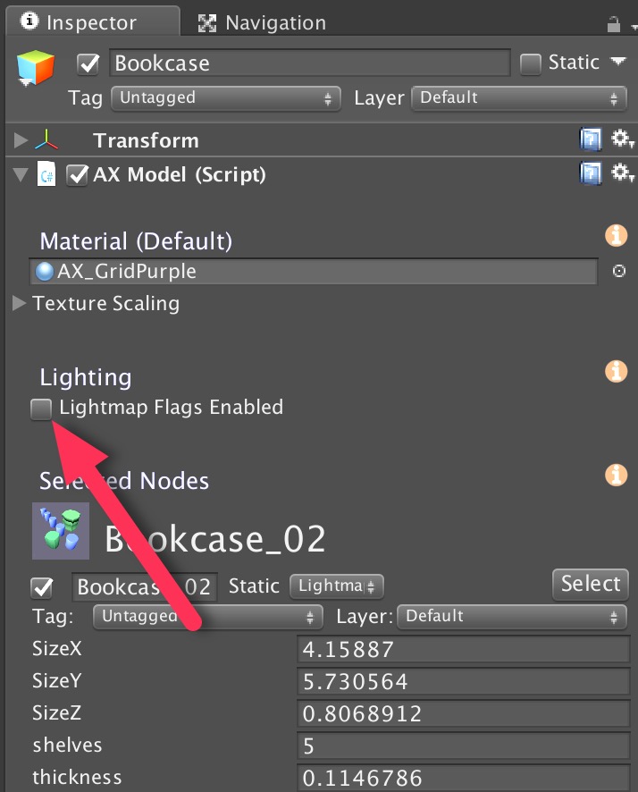 However, if you have a preference to leave “Auto” on, then you can temporarily disable Lightmap Static flags for your entire AX model by making sure the Lightmap Flags Enabled checkbox in the Inspector for the model is off. This means that, as AX generates GameObjects with meshes, it does not add the Lightmap Static flag to the the GameObjects and the light mapper will not be aware of the changes to the mesh. With this approach, you can model as much as you like, and then when ready to see it rendered with GI, you can click the Lightmap Flags Enabled checkbox.
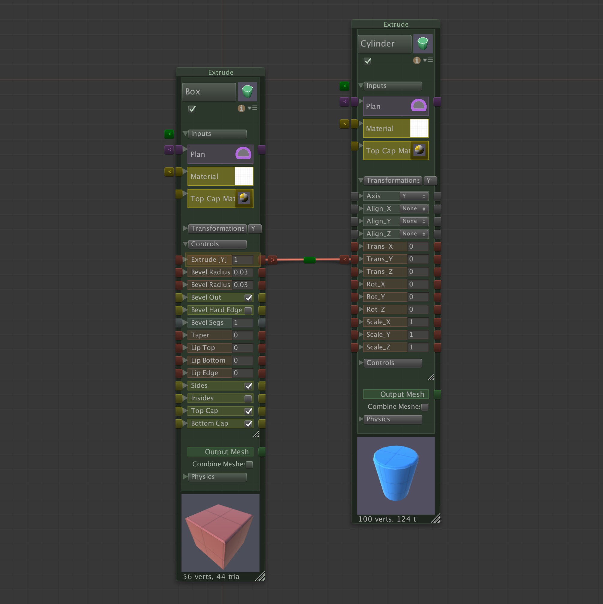
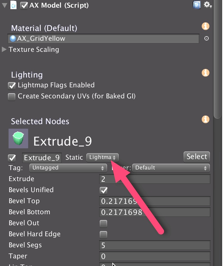 If a AX ParametricObject, such as the Extrude_9 in the figure to the right, is set to LightmapStatic (red arrow), then when a GameObject gets generated AX, its static flag will be set to Lightmap Static (so long as the Lightmap Flags Enabled is checked when the model is built), and the Unity GI system will treat it as such when rebuilding. This static flags setting is analogous to the flag options for any GameObject in Unity, with the difference being that the flag is set internally in the AX node and transferred to GameObjects when they are built by AX.
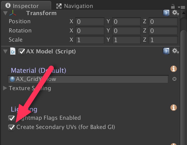

Recent Comments