PlanSweep
PlanSweep is the most generalized of the Mesher nodes and perhaps the most powerful. It uses two input Shapes to generate a mesh: a Plan Shape and a Section Shape. Either of these these input Shapes may be opened or closed, giving different characters to the meshes generated.
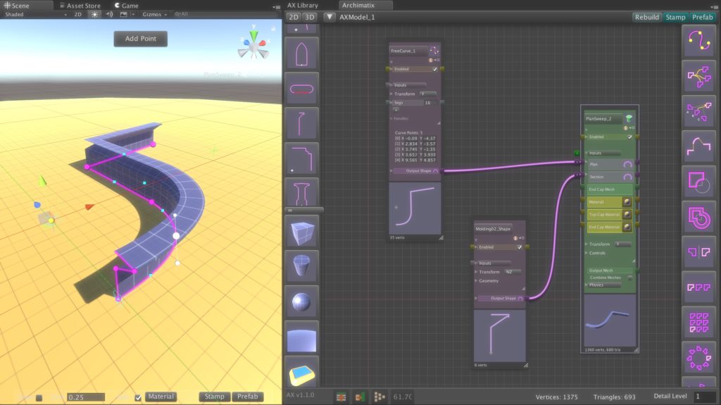
One way to think about how the PlanSweep node generates a mesh is to imagine the Section Shape being swept along the Plan Shape. At each vertex in the Plan, the Section is placed and polygons are created that span from the previous Plan vertex to the present one.
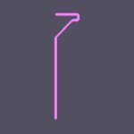
For the above example, a FreeCurve node has been fed into the Plan input of a PlanSweep, while the Section is a Shape from the Molding02_Shape.
In the above example, we see that both the Plan and the Section are open Shapes. PlanSweep will appear different in cases where one or the other, or both shapes are closed. Let’s take a look at some of these combinations.
Open Plan with Open Section
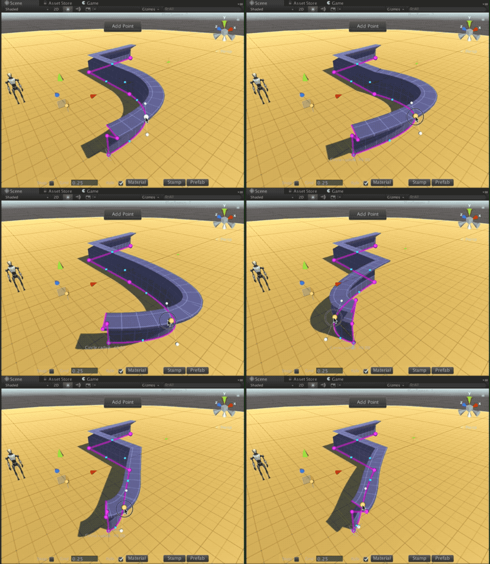
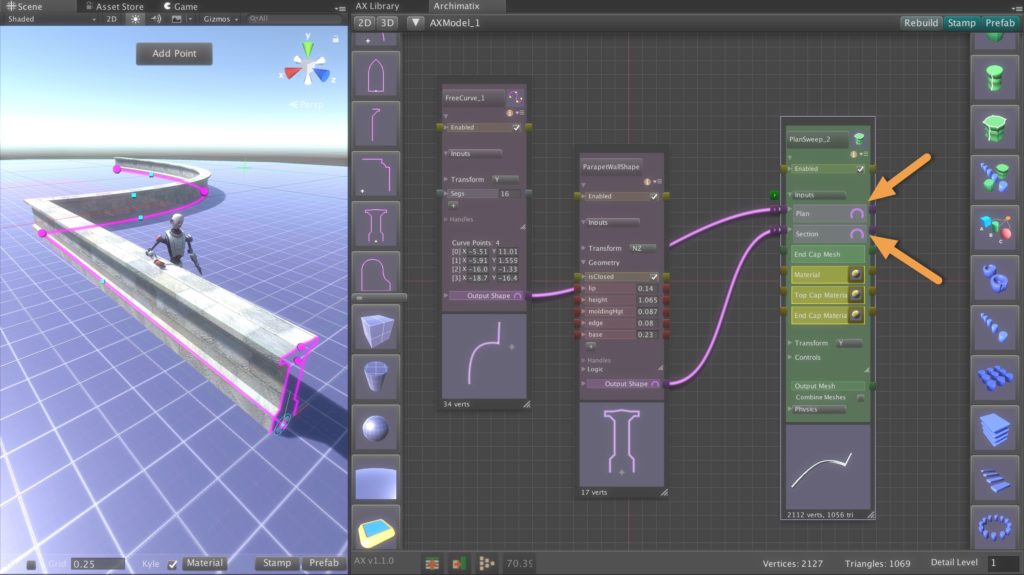
With a fence or wall, we often don’t need to see the bottom of the mesh, since it typically sits on the ground. In the example below, the wall uses an open Plan ( FreeCurve) and Section (ParapetWallShape from the 2D Library). This makes sense if the wall is terminated by a post or is perpendicular to another wall, leaving the ends of the wall out of sight.
The simplest way to control the shape state (open or closed) is to click on the toggle buttons to the right of the shape inputs, as shown with the arrows in the image above.
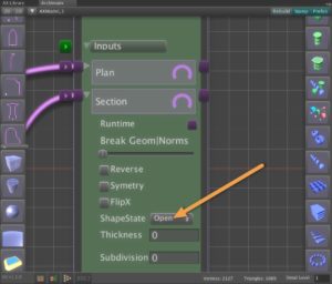
Shape state option.
You can also control the open/closed state of the shape with an option pulldown when the parameter foldout is opened for editing, as depicted in the image to the right. Note that altering the ope/closed shape state does not affect the state of the source Shape. It is common to have the shape open in one Mesher node and closed in another.
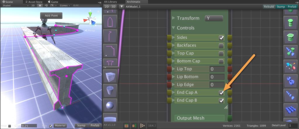
If the wall were to end in free space, not covered by some other object, you can choose to close the end caps. To do this, open the Controls for the PlanSweep, either in the node palette or the Inspector, and check the boxes for Cap A and Cap B. This will add polygons at the ends of the mesh without adding polygons at the bottom of the wall.
You may notice that there are also checkboxes for Top Cap and Bottom Cap. These caps normally make sense for PlanSweeps with closed Plans as we will see in the next section.
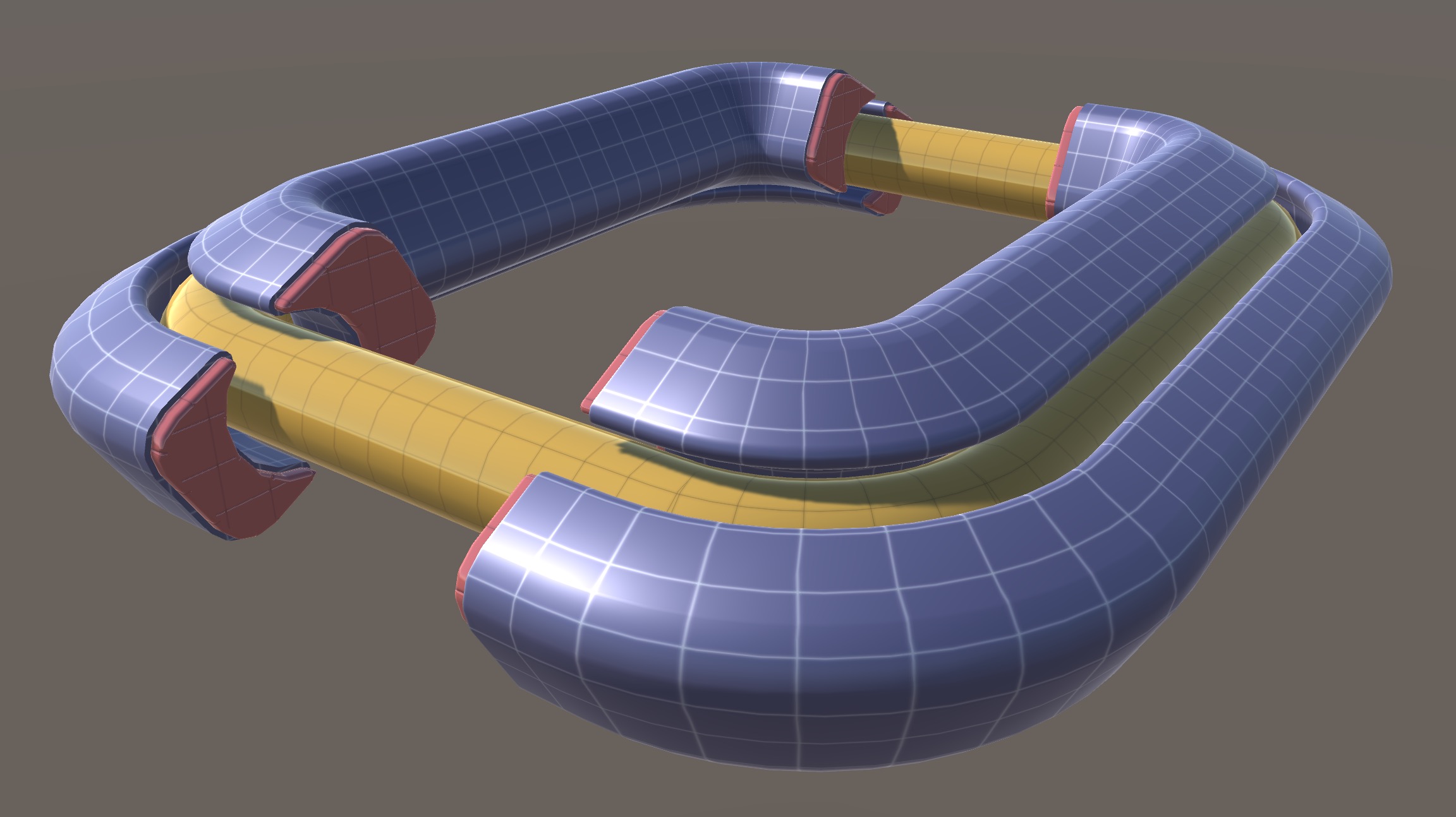
Another way to handle the end caps is to add from a PlanSweep with an open Plan is to attach an Extrude object that is generated with the same shape used for the Section, but for the Extrude it is input as the Plan. The Extrude can then be fed into the EndCapMesh parameter of the PlanSweep. The PlanSweep automatically creates Instances of the Extrude and places them at the end cap positions, as in the image below, where the red objects are the EndCapMeshes. The blue mesh is that generated by the PlanSweep and the yellow pipe is a closed Plan with a Circle as a Section.
Closed Plan with and Open Section
Among examples of an open Plan with a open Section are moldings and cornices, roof structures and sidewalks.
To make a building cornice for the following example, we use two Shapes from the 2D Library: for the Plan a Cross and for the Section a CymaRectaMolding. The CymaRecta Molding is an open Shape because the back of it (left side) is against the building wall.
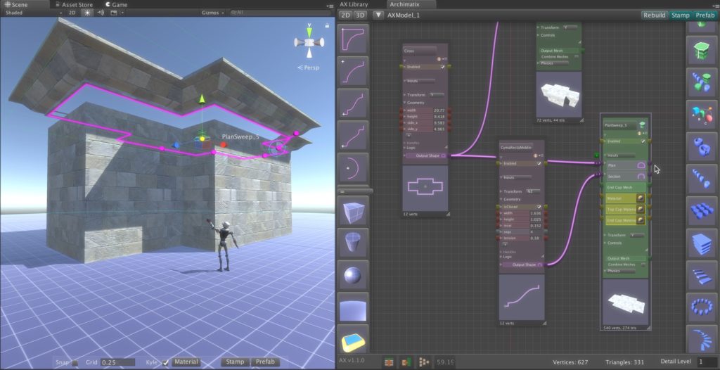
A building cornice generated by a PlanSweep node.
Open Plan with Closed Section
Among examples of an open Plan with a closed Section are tunnels and pipes.
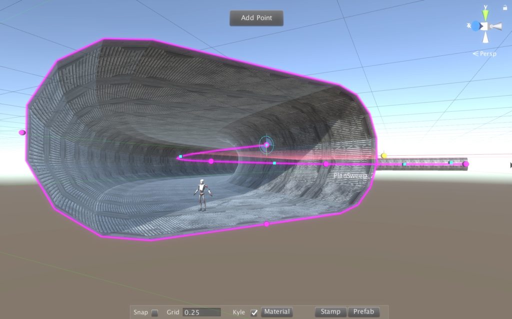
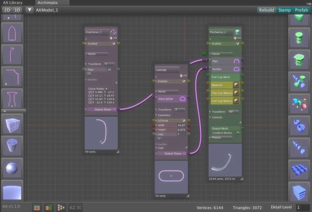
In the following example, we make a tunnel using a FreeCurve for the Plan and a Lozenge Shape from the 2D Library for the Section.
Pantheon (closed plan, closed section)
Cornice (closed plan, open section)
Railing (open plan, closed section)
Molding (open plan, open section)
City Buildings




Recent Comments