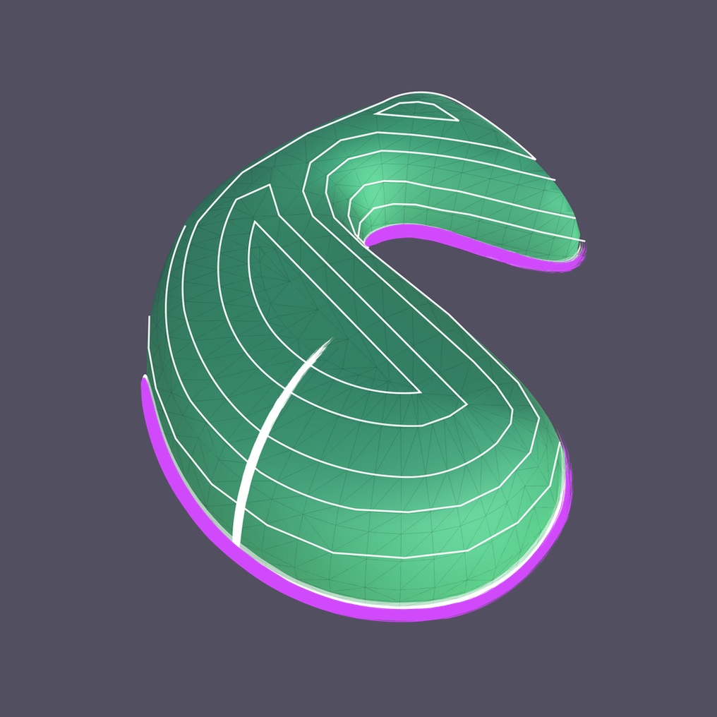
The ContourExtruder extrudes a Plan using a Section Shape. It uses the x-value of each point in the Section Shape to create a contour by offsetting the Plan and then it lifts that contour up to the y-value of the same point. Each contour bridges to the next to create the resulting mesh. The effect is similar to a topographic landscape model.
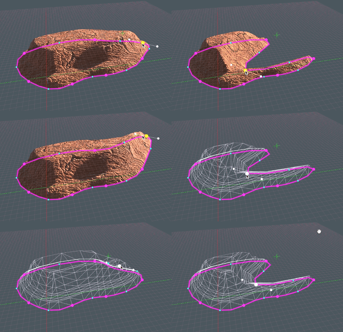
The ContourExtruder differs from PlanSweep in that the latter creates sectional ribs at each point in the Plan Shape. While the PlanSweep mesh is great at generating UVs that run around the mesh in the horizontal direction (e.g. a brick texture), if the Plan pinches in, the mesh could have errors at the corners, as is the case with the background mesh in the image below. A benefit of of the ContourExtruder is that the resulting form will never have pinching errors found when a Section is simply extruded around a Plan.
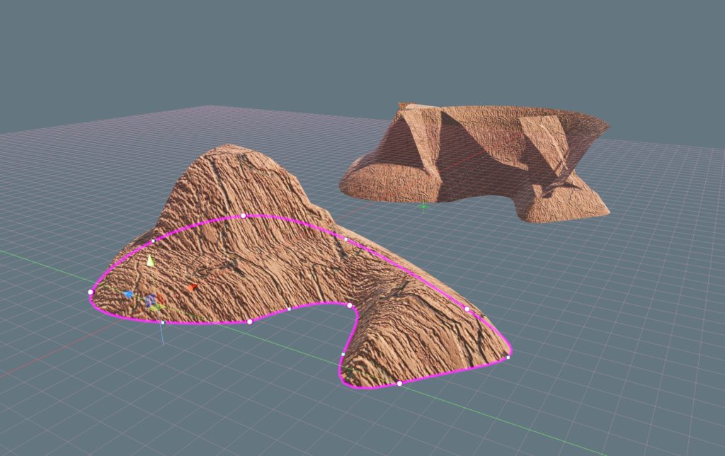
The ContourExtruded mesh will only use the parts of the Section Shape that it can given the span of the Plan at that point. Thus we see a stort of terrain instead of a surface of consistent height.
The UVs of the ContourExtruder are projected on to the surface of the mesh in a direction normal to the Plan. This is also different than PlanSweep in that textures will not be wrapped around the sides. In this sense, ContourExtruder is more natural or organic, while PlanSweep is more “architectural.”
Restrictions on the Section Shape
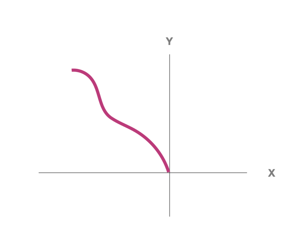
Currently, the Section Shape must be entirely in the negative X and slope continually to the left. While the Shape may dip up and down on the Y-axis, it can not back track horizontally.
A good use of ContourExtrude is for Plans that are letters and symbols. For example, in the “A” of the Archimatix logo, the verticals are wider than the horizontal line, so they extrude higher.
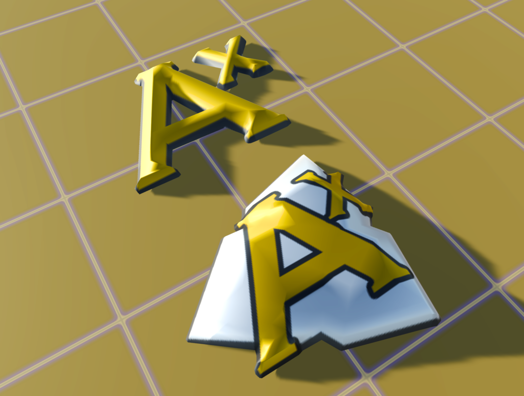
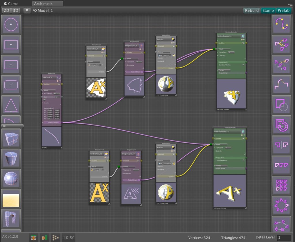
In the example above, the Plan Shapes for the logos were created by the ImageShaper node.

Leave a Reply
You must be logged in to post a comment.